Our Innovations - Electricity from the suspension - function description
Join us in the technological future of electric and hybrid cars.
Become an investor, sponsor or participant in this new technology of the future. Invest in the already-granted US and European patents for the development of the system for series production and manufacture.
Through your involvement, you will receive a lucrative investment in our patents and in future licensing evenues.
Feel free to contact us via email:
Further information, including technical descriptions and an animated video of the functional principle, can be found here.
Description of the invention
 The automotive industry is currently under increased political pressure to realise the prescribed C02 limit of 120 g/km for internal combustion engines by 2015.
For decades the optimal alternative, that is, genuine electric cars, has been ignored and hydrogen has been favoured as the energy source of the future.
The automotive industry has now been surprised by enormous falls in turnover, with losses in the billions, and is looking for ways out of the misery with hybrid and electric cars which use lithium-ion batteries as the energy store.
 This is an expensive and less than ideal technical fix, with which the basic, probably unsolvable problems remain, that is, insufficient battery storage capacity, inadequate service life and excessively long charging times, high prices and weight, as well as excessive volume. In contrast, the present invention, with the state-of-the-art technologies available today and the inventive improvements and innovations, offers a comprehensive energy concept in order to supply energy to the vehicle in a novel manner while driving.
This is realised by in-vehicle energy recovery from conversion into electricity of the kinetic energy present during driving resulting from the movements of the suspension of the vehicle wheels.
The amount of the energy produced autarkically by the vehicle with the methods of this invention is fully sufficient for the energy consumption of the vehicle, so that a car battery of relatively modest capacity, which does not have to be recharged externally, is sufficient.
The electric car thus has unlimited range and no operating costs at all, which is a sensational innovation and an ideal selling point .
FUNCTIONAL DESCRIPTION (summary)
Conversion of the kinetic energy from suspension movements into electricity
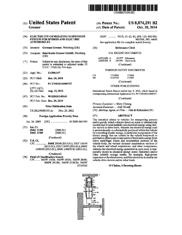
The principle functioning of the novel hydraulic suspension and damping element (2) during the conversion of kinetic energy from the suspension movements into electricity is described below with a simplified diagram in Fig.11 and Fig.12.
This invention employs a novel vehicle suspension and damping system, which uses none of the previously customary energy- absorbing elements (steel spring or airbag and hydraulic shock absorber), but a special, inventive hydraulic suspension and damping element (2) which is coupled mechanically, hydraulically or pneumatically to a special electricity generator ( 7 ) or is combined as a common component.
In order to prevent misunderstandings, it must be noted that this technology is of Course not "perpetual motion" or intended to be a direct conversion of gravity into electricity.
This is because the energy required for producing electricity is supplied externally in sufficient quantities constantly during driving in the form of the previously unused kinetic energy of the vehicle wheel suspension movements, which is converted into electricity.
This kinetic energy results from the vehicle weight, which is in turn caused by the earth's gravitation.
Although the conventional steel springs or airbags including hydraulic shock absorbers are omitted, their known technical functions including self-levelling suspension and the "active chassis" are retained.
The suspension and damping element (2) with the integrated electricity generator (7) converts the kinetic energy of the bouncing vehicle wheels (1) into electricity in considerable quantities with a very good level of efficiency.
The amount of electricity produced is congruent with the vehicle weight. The greater the weight, the higher the electricity yield.
The amount of electrical energy produced in this way can be determined as an approximate average value using a simplified theoretical consideration as follows.
If the electric vehicle weighs two tonnes, for example, and each wheel has one of the inventive linear generators (7), the amount of electricity generated per kilometre driven is calculated as follows :
Assuming very conservatively that each of the four wheels has an average suspension travel of + / - 10 mm per decimetre of distance travelled, the suspension travel is 200 m per wheel over one kilometre travelled.
The total suspension travel for all four wheels is therefore 800 m per kilometre. At the assumed weight of 500 kg (approx. 5,000 N) per vehicle wheel (I), which acts as kinetic energy on the linear generator (7), this produces energy generated in this manner of 4,000,000 Nm (4 MNm) per kilometre.
This is approx. 1.1 kWh per kilometre travelled. Assuming (unrealistically high) energy conversion losses of 50%, at least 0.5 kWh/km or 50 kWh per 100 km travelled remain.
This is more than enough energy, not only for the electric drive motors but also for the additional consumers such as heating, air conditioning etc., which can be buffer-stored in batteries and / or capacitors.
In comparison: The amount of electricity which is necessary on average for the drive motor of an electric car is for example 12 to 18 kWh per 100 km travelled for the 185 kW-rated 3-phase asynchronous motor in the "Tesla Roadster1'made by the company Tesla Motors in the USA.
In the drawings Fig. 11 and Fig. 12, which are not to scale, the following elements are labelled:
Vehicle wheel (1)
Suspension element (2)
Vehicle body (3)
Vector, direction of travel (FR)
Road surface (FB)
Road surface elevation (FB.1)
Road surface depression (FB.2)
Body height , normal (H.norm)
Body height, above normal (H.pos)
Body height, below normal (H.neg)
Vector, weight during compression (G.einf)
Vector, weight during extension (G.ausf)
Vector, weight at normal height (G.norm)
Vector, vertical force, positive direction (K.vert.pos)
Vector, vertical force, negative direction (K.vert.neg)
Travel, compression with road surface elevation (A>B)
Travel, extension with road surface elevation (B>C)
Travel with damping rebound 1 (C>D)
Travel, extension with road surface depression (E>F)
Travel, compression with road surface depression (F>G)
Travel with damping rebound 2 (G>H)
Fig. 11 shows the movement of the vehicle (3) in the direction of travel (FR). The road surface elevation (FB.1) begins at position (Al and extends as far as position (C). The vehicle wheel (1) moves over the distance (A>C), with the travel (A>B) effecting a compression.
At position (B) the vehicle wheel (1) reaches the highest point or the maximum compression travel. The forces acting here increase progressively as the vector (K.vert.pos) shows. They act counter to the weight force, shown as vector (G.norm), which is exerted via the suspension element (2) with the variable hydraulic pressure on the vehicle wheel (1).
During the distance (B>C), the vehicle wheel (1) makes an extension movement and reaches the normal level of the road surface (FB) again at position (C). Electricity is generated in a known manner by induction in the coupled linear generator (7) both during the compression movement and during the extension movement of the vehicle wheel (1).
If the damping effect by the magnetic counter force of the linear generator (7) during electricity production is not sufficient, the vehicle wheel (1) makes a few weakening spring after-movements, which are absorbed and damped by the elastic vehicle tyres.
In the event of excessive residual forces and insufficient damping by the tyres, the body is lifted vertically out of its normal body height (H.norm) to the above-normal body height (H.pos), as a result of which the excess residual energy is consumed.
When the vehicle wheel (1) moves from position (A) to (B) it moves vertically upwards, as a result of which the hydraulic pressure is increased because the additional force (K.ver.pos) is exerted on the pressure cylinder (DK-4).
This is registered by the travel sensor (WS) and/or the pressure sensor (DS) and communicated to the control electronics (16). The latter outputs the signal to reduce the pressure or switches the associated pressure chamber (DK.4) to the pressureless state by means of the valve. The compression movement (K.vert.pos) of the vehicle wheel (1) can thus take place without resistance, and the linear generator (7) which is activated in the process can convert virtually 100% of the kinetic energy during compression into electricity until the vehicle wheel (1) has reached position (B).
In the process, this electricity generation produces the magnetic counter force (K.mag) in the linear generator (7), in accordance with the known physical induction laws, which magnetic counter force is effective in the opposite direction to the compression movement and damps it until the speed and movement at position (B) is zero.
The damping effect by the magnetic counter force (K.mag) can be varied as required within a wide range by the control electronics (16) with very fast reaction speeds by means of a variable regulation of the current in accordance with the stored parameters and circuit algorithms, as a result of which the spring rating and thus the suspension properties and road position can be adapted automatically according to requirements.
As the vehicle ( 3 ) moves further in the direction of travel (FR) from position B to C, the vehicle wheel (1) bounces back from the maximum position B until it reaches the normal level of the road surface (FB) at position C.
This extension movement is also used to obtain electricity and is ef fected by the vehicle wheells (1) own weight (gravitation) and that of its components (tyres, rim, hub, brake, suspension). The forces which are effective here are shown in the diagram Fig. 11 with the vectors (K.vert.neg)
If required, the control electronics (16) can have a positive or negative (accelerating or braking) influence on the extension by means of the pneumatic pressure, which correspondingly has a positive or negative effect on the total efficiency of the system when obtaining electricity.
When the vehicle wheel (1) has reached position C, the normal force, the vector weight (G.norm) acts on it. The vector weight (G.norm) is approximately 25% of the total vehicle weight per wheel with equal axle load distribution. In this electricity generating system, a greater vehicle weight is advantageous for the efficiency.
With a road surface elevation or depression of small area, at least two linear generators (7) are activated in the associated front and rear wheel when driving over it. If the elevation or depression extends over the whole width of the road surface or at least the vehicle width (lane width), all the linear generators (7) are activated in all four vehicle wheels (1).
The distance from C to D is the rebound region, when any kinetic residual energies are still present which have not been .3 sufficiently damped. In the region from C to ~ . 1 / ~ . 2 / ~the vehicle wheel (1) may still have the tendency to bounce out again. This inhibits the now flat road surface (FB) so that residual forces which are still present either must be compensated by the control electronics (16) by means of the hydraulics and/or the tyres of the vehicle wheel (1) absorbs these forces and deforms and/or the vehicle body is lifted positively (vertically) in an undesired manner from the normal height (H.norrn) to the height (H.pos). The vertical negative forces which are effective here mean that the tyres of the vehicle wheel (1) continue to keep in contact with the road surface (FB) and do not lift off temporarily, which would be detrimental to driving safety.
In the case of tyre deformation and a vertical body movement, the associated kinetic or primary components of the gravitational energy are of Course lost for electricity generation with the linear generators (71, for which reason the programming of the control electronics (16) must ideally be designed in such a manner that this is avoided.
In the alternative case, when the vehicle wheel (1) travels through a dip in the road surface or a pothole (distance E to G in Fig. 12), the function of the electricity recovery is in principle identical.
Fig. 12 shows the movement of the vehicle wheel (3) in the same direction of travel (FR). The road surface depression (FB.2) begins at position E and stretches until position G. The vehicle wheel (1) moves over the distance (E>G), with the vehicle wheel (1) executing an extension movement over the distance (E>F).
At position F the vehicle wheel (1) reaches its lowest point or the maximum extension travel. The forces effective here increase progressively as the vector (K.vert.neg) shows.
All the force (G.norrn), shown as vectors (K.vert.neg), which correspond to approx. 25% of the total vehicle weight, acts as kinetic energy on the linear generator (7), which then converts this kinetic energy and the associated components of the primary gravitational energy into electricity, with the magnetic counter force (K.mag) which arises during the electricity induction counteracting this extension movement and exerting a movement- damping effect, which corresponds in principle to that of a customary hydraulic shock absorber and furthermore can be adapted in its effect (damping force) very quickly and within very wide ranges by the control electronics (16) in a variable manner according to requirements. When the vehicle wheel (1) has reached position F, the control electronics (16) receive information through the travel sensor (WS) and pressure sensor (DS) that the extension movement has finished.
The control electronics (16) then switch the associated hydraulic chamber (DK) to its pressureless state so that the subsequent compression movement over the distance from F to G is without hydraulic resistance and the linear generator (7) can use virtually 100% of the kinetic energy from the forces of the vector (K.vert.pos) for obtaining electricity.
When position G has been reached, the vehicle wheel (1) is again at the normal road surface level (FB). The extension movement (K.vert.pos) must be terminated here by the extension forces being damped to the value Zero by the magnetic induction counter force (K.rnag), as otherwise rebound movements of the vehicle wheel (1) would take place over the distance from G to H, which would be detrimental for the road position of the vehicle (3).
The control electronics (16) must therefore adapt the magnetic counter force (K.rnag) correspondingly to requirements by corresponding variation of the strength of the coil current in the linear generator (7), in order to ensure by means of the induced strengthening or weakening of the induced magnetic counter force (K.mag) that the extension movement of the vehicle wheel (1) has finished at or shortly before position G, so that it remains on the road surface (FB) and does not rebound or lift. If, in exceptional cases, this should not be sufficient, the control electronics (16) can actively suppress the undesired rebound by corresponding hydraulic counter pressure measures as a result of electronic activation of compensatory counter forces (K.hydr), which cancel out the residual energies.
3D-Animation
This video will show you a 3D-animation of the "electricity-generating suspension system" for hybrid and electric vehicles.
Technical drawings
If you need further specifications, please leave us a message on our contact-form.
 |
 |
 |
 |
 |
 |


